
1911 LMC Pictures
Add Your Photos!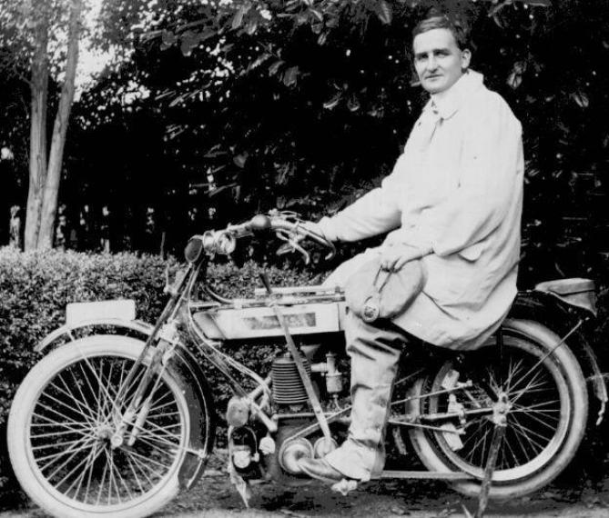
Many thanks to Russell Pencin for sending this picture in. And thanks to Leon for identifying it as an LMC of about 1911, built by the Lloyd Motor Engineeering Co., one of W.J. Lloyd’s ventures.
“The pivotted bottom link fork is an LMC feature (although I think it may have been made by Chater Lea), as is the dual brake shoe arrangement on the belt rim. I’m not sure what the gear/free-engine device is, but it looks to be one of the ones that spreads the flanges of the front pulley against spring pressure. You get a bit of a gearing effect with devices like this, but not much because the belt loosens as the gear is reduced. There is often a free-running ring at the bottom of the pulley groove, so that with the flanges wide apart the belt sits on the ring and does not drive. A form of clutch, but pretty hard on the belt at take off.
The story goes that many/most LMCs were exported to the colonies. This may be true: they are not particularly rare out here in Australia.”

I believe that is a 1913 model from the frame design. Quite a number here in NZ. but have valances on the mudguards indicating “colonial’ export models were sent here. I have other photos of the same gentleman on the bike and a 1913 sales catalogue. In 1913 Lloyd curved the end of the tank and lowered the seat
My one is engine 1323G, frame 1454G. (G indicating 1913 models) has 2 speed countershaft gearing. Other options were Lloyds patented “Auto Varia’ as per your picture and 3 speed Sturmey Archer axle gearing
I have a 1911 model. Mine has matching frame ang engine numbers.
I’d agree with Leon’s assessment of the year.
The pulley and lever combination looks like LMC’s ‘Auto-Varia’ pulley (patented 1908).
The inner flange was part of the main pulley boss, and the outer flange was pressed inwards by springs which were of suitable weight that when the motor was pulling hard (uphill, for instance), they’d compress and allow the pulley faces to open for a lower gear.
The handle pivots at the top of the crankcase, and has a roller wheel at the lower end. This was a sort of ‘manual over-ride’ which the rider could jam in between the pulley flanges to force them apart, either to lower the ratio, or to achieve a ‘free-engine’ by opening them wider than the belt.
A notched gate attached to the top tube gave some options for setting the lever.
There’s no obvious mechanism to take up the belt slack at low ratios, but it lasted as a fitment/option for a few years.